
How to Choose an Impulse Voltage Generator in 2026?
Choosing an Impulse Voltage Generator in 2026 requires more than comparing maximum voltage ratings. The right system must match your test objects, waveform requirements, laboratory space, and verification procedures. A generator designed for lightning impulse testing may not suit switching impulse applications. That distinction matters.
Begin with the required impulse shape, such as the standard 1.2/50 μs waveform. Check voltage range, energy capacity, charging speed, and load behavior under actual test conditions. A larger rating is not automatically better. It can increase cost, floor-space demands, and safety complexity. Consider the test specimen carefully. A transformer bushing, cable termination, or power electronic module may respond differently to the same nominal impulse.
Practical experience also reveals details that brochures often simplify. Ask whether the control system records voltage, current, timing, and oscillation clearly. Confirm that measurement dividers, grounding systems, and calibration services support reliable results. Verify alignment with current IEC or equivalent laboratory standards, then request documented test data from the manufacturer. Specifications should be independently reviewed.
The choice is rarely obvious. One overlooked issue can delay commissioning. Some suppliers offer impressive peak voltage figures but provide limited support for routine maintenance or waveform correction. Others may deliver strong hardware with weak software documentation. That gap deserves attention. A responsible selection process compares technical evidence, operator training, service response, and total ownership cost. It should also include a realistic risk assessment before installation. In 2026, the best generator is not simply the most powerful model. It is the one that produces repeatable, traceable impulses for your specific testing work.
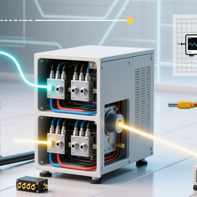
Define the Test Objective: 1.2/50 μs Lightning or 8/20 μs Current Impulses
Choosing an impulse voltage generator starts with the test objective, not the advertised peak voltage. For insulation coordination, the target is usually a 1.2/50 μs lightning impulse. IEC 60060-1 defines this waveform with a 1.2 μs front time and a 50 μs time to half-value. The generator must therefore control wave shape, overshoot, polarity, and measurement accuracy. IEEE Std 4-2013 also emphasizes calibrated voltage measurement and repeatable impulse parameters. A 500 kV rating alone proves little.
The requirement changes for an 8/20 μs current impulse. This waveform reaches its crest in about 8 μs and falls to half value near 20 μs. IEC 62475 identifies it as a standard high-current test waveform for surge-protection evaluation. Select the generator by peak current, transferred charge, source impedance, and test-object inductance. A short, wide conductor can matter more than another impressive specification. In practical laboratory work, failed tests often come from poor grounding or unsuitable shunts, not insufficient generator power. Check the oscilloscope bandwidth and calibration records. Then verify the waveform under the actual load. That step is easy to skip. It should not be. Reports from the International Electrotechnical Commission and IEEE remain more reliable than simplified catalogue tables, although even those standards require engineering judgment for unusual equipment.
How to Choose an Impulse Voltage Generator in 2026? - Define the Test Objective: 1.2/50 μs Lightning or 8/20 μs Current Impulses
| Test Objective | Standard Impulse | Primary Quantity | Typical Test Application | Key Waveform Parameters | Generator Selection Criteria | Measurement and Safety Priorities |
|---|---|---|---|---|---|---|
| Lightning impulse insulation test | 1.2/50 μs Standard switching and lightning impulse voltage waveform | High-voltage impulse | Insulation coordination and dielectric withstand testing of electrical equipment, insulation systems, bushings, transformers, cables and other high-voltage components | Front time: approximately 1.2 μs Time to half-value: approximately 50 μs Polarity: positive, negative or both, depending on the test plan | Select a voltage impulse generator with sufficient peak voltage, charging voltage, energy and test-object capacitance range. The output circuit should support waveform adjustment and low-inductance connections. | Use a calibrated high-voltage divider and impulse recorder. Provide controlled earthing, adequate clearance, interlocks, discharge equipment and a defined approach boundary. |
| Surge protective device current test | 8/20 μs Standard current impulse waveform | High-current impulse | Surge protective devices, varistors, gas discharge devices, semiconductor protection components, bonding conductors and lightning-current protection paths | Front time: approximately 8 μs Time to half-value: approximately 20 μs Peak current and transferred charge depend on the selected test level | Select a current impulse generator based on peak current, open-circuit voltage, short-circuit current, load impedance, required repetition rate and the device’s expected energy absorption. | Use a calibrated current shunt or suitable current transformer with adequate bandwidth. Keep the high-current loop short and rigid, and verify thermal, mechanical and arc-flash controls. |
| Combined voltage-current surge test | Application-specific combination of voltage and current impulses | Voltage and current simultaneously or sequentially | Complete surge protection assemblies, coordinated protection systems and equipment exposed to both insulation stress and conducted surge current | The voltage and current waveforms are influenced by the generator, source impedance, test object and connection layout. They should be verified at the test terminals. | Consider a dedicated combination-wave system or coordinated voltage and current sources. Confirm peak voltage, peak current, source impedance, coupling method and energy delivered to the test object. | Synchronize measurement channels and confirm insulation, grounding and trigger performance before applying full energy. Record both applied and residual waveforms where applicable. |
| Generator output capability | Not defined by waveform alone | Peak value, energy and repetition capability | Any impulse test where the nominal waveform is correct but the generator may not deliver the required stress to the actual load | The connected test object can change rise time, decay time, peak value and oscillation. Generator ratings should therefore be checked with the intended load, not only under open-circuit conditions. | Compare peak voltage or current, stored energy, effective source impedance, capacitance or inductance range, charging time, trigger stability and maximum permissible repetition rate. | Check the complete measurement chain, including sensors, dividers, cables, bandwidth, grounding and calibration uncertainty. Use acceptance limits defined by the applicable test standard. |
| Waveform verification | 1.2/50 μs or 8/20 μs nominal shape | Time-domain conformity | Routine validation, type testing, laboratory commissioning and troubleshooting of impulse test systems | Confirm front time, time to half-value, peak value, polarity, overshoot, oscillation and reproducibility. The permissible tolerances depend on the applicable standard and test configuration. | Choose a generator with practical adjustment of resistors, inductors, capacitors or equivalent control elements so the required waveform can be obtained at the test object. | Measure at the defined reference point using traceable instruments. Document the test circuit, load condition, waveform parameters, environmental conditions and any deviations. |
| Decision rule for 2026 selection | Define the objective before selecting the generator | Match source type to stress type | Prevent purchasing a voltage impulse generator for a current impulse requirement, or a current source for an insulation withstand requirement | A 1.2/50 μs test is principally a voltage insulation test; an 8/20 μs test is principally a current surge test. Their generators, sensors, connection layouts and safety controls are different. | First specify the waveform and test object. Then calculate the required peak value, load range, energy, repetition rate, measurement bandwidth and future expansion needs. | Require documented calibration, interlocked operation, emergency discharge, remote control where appropriate, guarded test areas and procedures consistent with the laboratory’s electrical safety program. |